Mori Seiki X 4 Mc’s (Ford Engine Line)
Opening: The automotive sector has had another very busy year, and our year in support of JLR & Ford suppliers has been equally hectic. Working with our customers we have been able to perform numerous planned maintenance projects during scheduled downtimes & shutdown periods.
2015 Summer shut down we undertook a refurbishment project of a Fanuc robot loaded cell of DMG Mori Seiki machines, which manufacture a major component of the Ford engines. The project started back in April during the Easter period, high production volumes meant the team at CNC Repair could only have the cell between 7pm & 7am on the Friday, Saturday & Sunday nights. The machines were taken through our comprehensive service plan to ensure the machines were kept in a good order & to identify any potential issues which could stop the line for an extended period.
On completion, a report detailing the current condition of all electrical, mechanical, hydraulic & pneumatic aspects of the machines was produced, this was then presented along with a list of recommended actions to be taken
With high levels of production, it was agreed that the mechanical transmission aspects of the machines posed the highest risk of extended downtime should failure occur.
Key areas:
- Replace Z axis slideway rails & ballscrews on all 4 machines
- Replace X axis slideway rails & ballscrews on all 4 machines
- Replace Z axis pinder guards on all 4 machines
- Replace Y axis pinder guards on all 4 machines
- Overhaul of hydraulic tanks on all 4 machines
- Overhaul of lubrication system including lines on all 4 machines
- Replace tool change door, rails, cylinders
- Deep & thorough clean of tool change mechanisms, replacement of cylinders, switches & nylon guides on all 4 machines
- Deep & thorough clean of the tool magazine, pockets & re-tension of the magazine chain on all 4 machines
- Overhaul & clean of the coolant tanks, filters, spray bar on all 4 machines
- Replace the operator safety glass, all 4 machines
Careful consideration went into the project plan, of which the areas mentioned above, would be carried out & in what sequence to ensure that the machines would be returned to production in exactly 2 weeks. Heavy lifting equipment needed to be planned to be brought onsite in the form of a versa lift, to lift the Y axis columns to enable our Engineers access to the X axis ballscrew & slideway rails. It was deemed that the level & volume of work would only be possible to complete (on time) would be to have teams of our Engineers working 24 hours a day for 14 days.
Work began on Saturday stripping back the guarding to allow for the first element to begin, the removal of the Z axis slideway rails & ballscrew on all 4 machines.
This included removal of the B-axis table, to allow sufficient access to the rails and ballscrew. This also created issues with the wiring being undisturbed for a long period of time resulting in brittle cables. We replaced all terminations and in some cases re-wired the B-Axis. Pictures show a time lapse of the work carried out on the Z axis transmission:
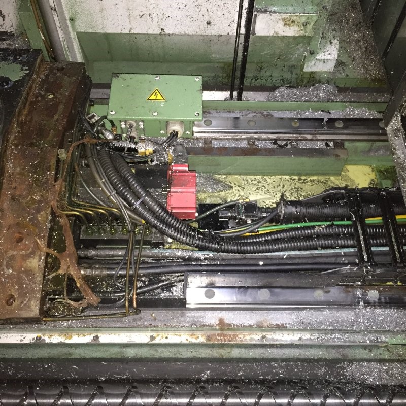
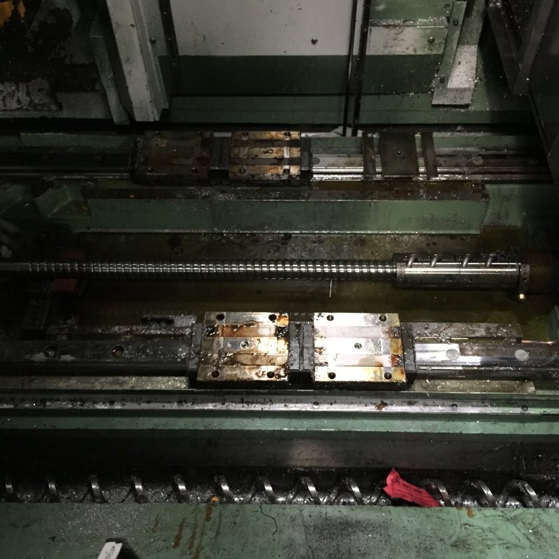
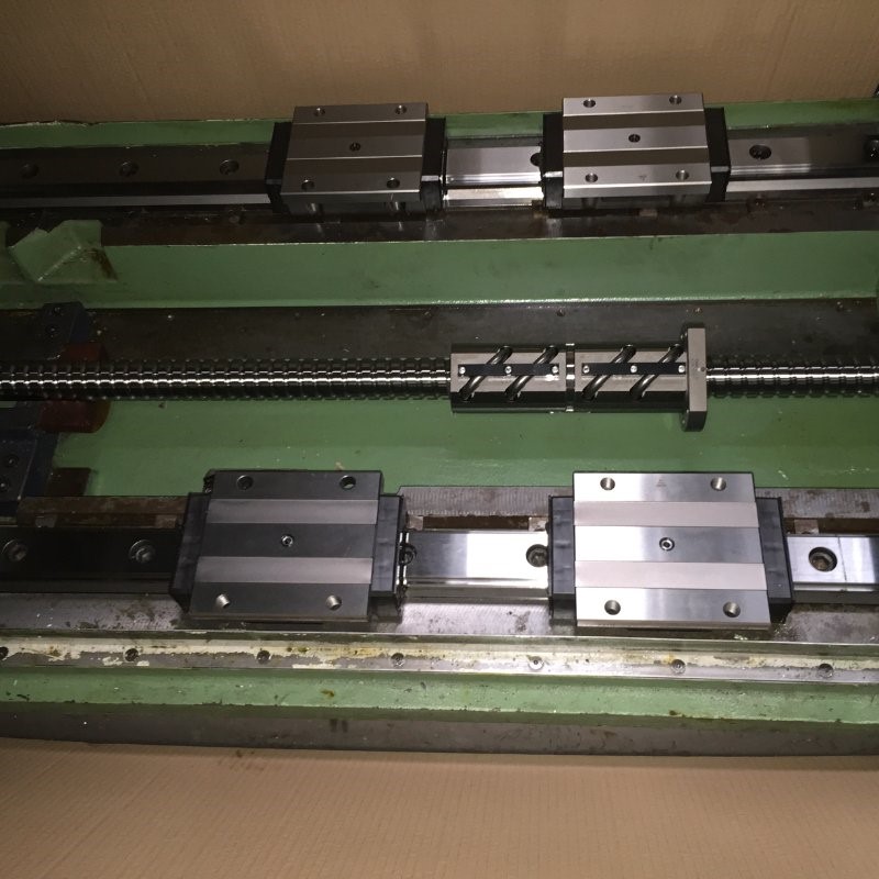
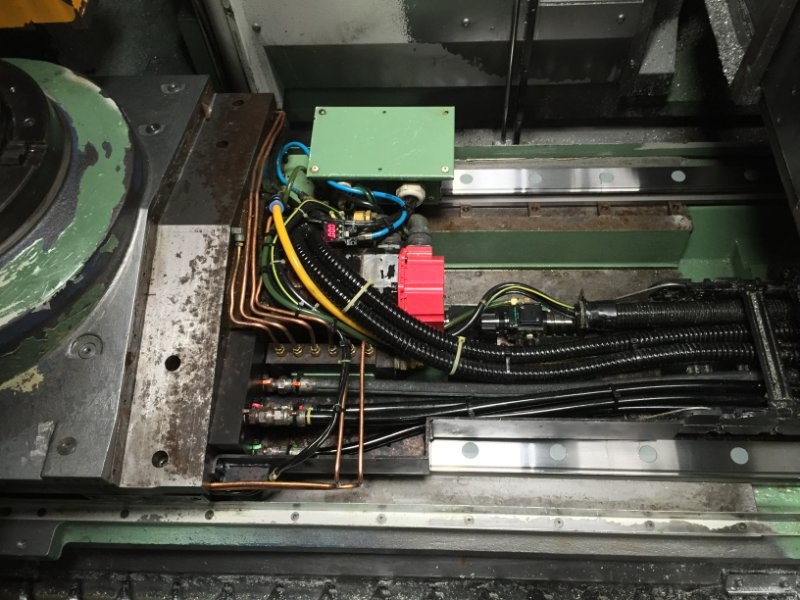
Next key area was to thoroughly clean the tool magazine, tool changer mechanisms. Rebuild with new cylinders, guides, switches, nylon strips, springs & re-tension of the magazine chain. We then touched up the pick and place position on the magazine to allow for smoother transactions between tool changes. Pictures show a time lapse of the work carried out on the magazine and tool changer:
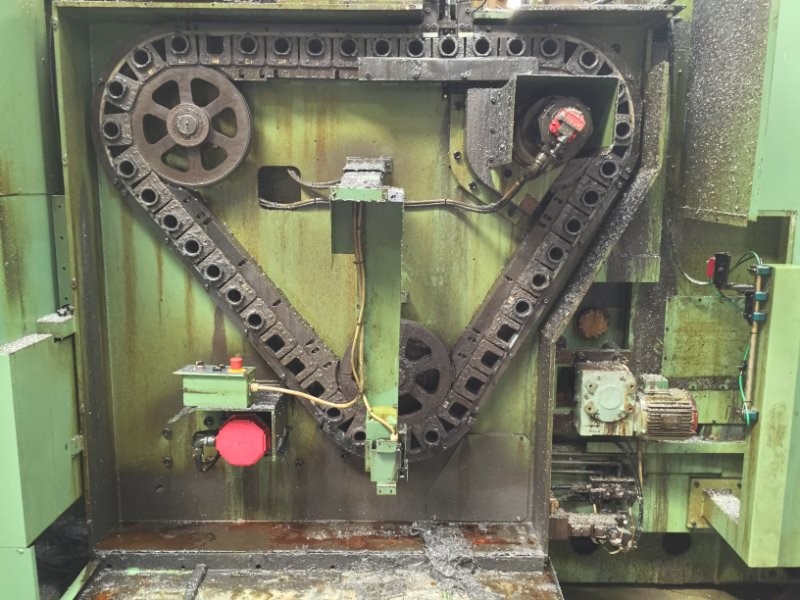
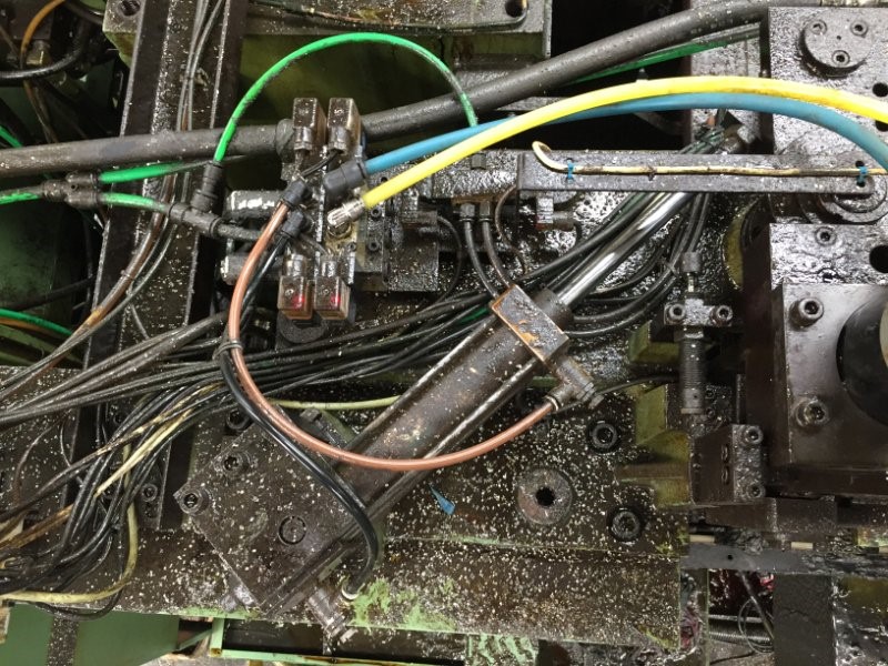
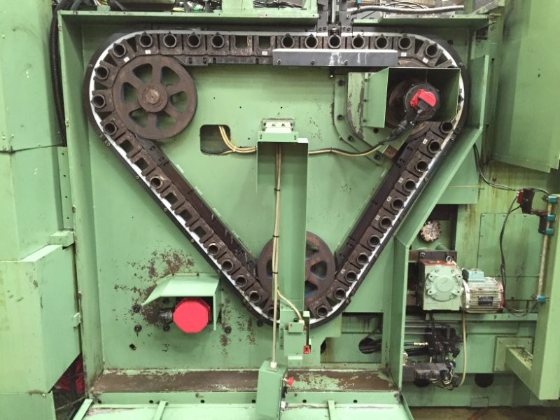
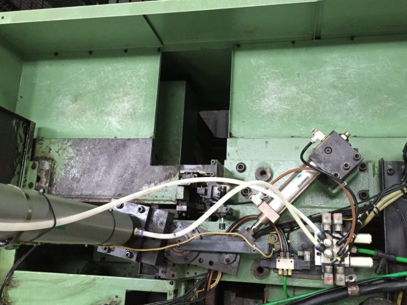
Next key area was to remove & replace the X axis ballscrews & slideway rails. This was only accessible with the Y-axis column raised in the air and supported from underneath. Pictures show a time lapse of the work carried out on the X axis transmission:
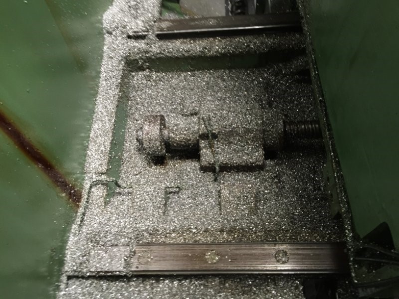
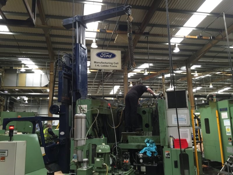
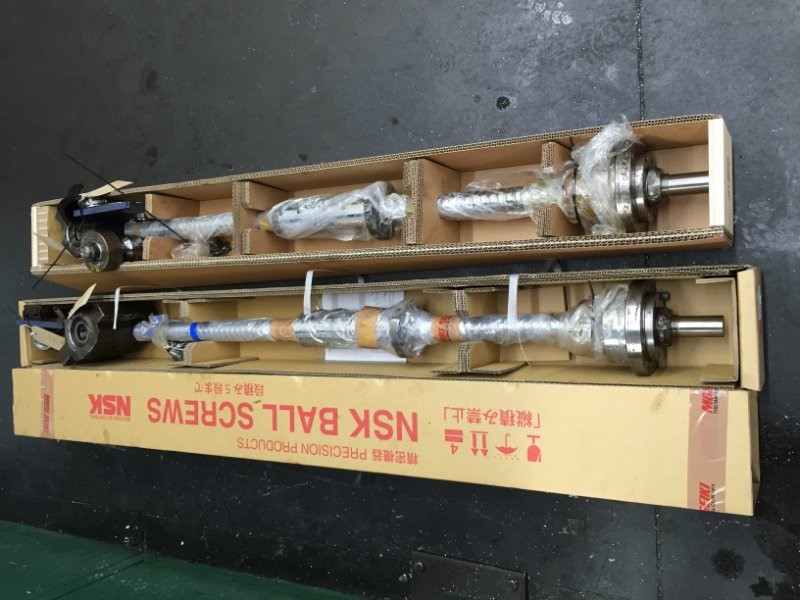
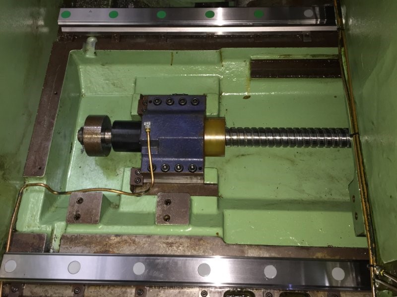
Next key area to address, was to remove the tool change door, rails & cylinder & replace. This allowed us 3 days to complete various remaining items & begin machine testing. All relevant data was inserted into the corresponding parameters and checks were made. Once we were satisfied with the pick and place of the tool changer and pallet change positions. This was handed back to production to set the job up to the new co-ordinates.
Contact
Tel:
0800 043 1800
Email:
support@cncrepair.co.uk
CNC Repair (UK) Limited
Unit 4 Spalding Road Business Park,
Bourne,
Lincolnshire PE10 9LF
Navigate
DMG Spindle Repair
When it comes to CNC machines, the spindle is a critical component that plays a vital role in the...
HSD Spindle Repair
When it comes to precision machining and high-speed cutting operations, many manufacturers choose...

